Posts

Showing posts from August, 2020

Magnetostrictive transducer

Image
Construction and working Initially interrogation pulse is sent through a ferromagnetic waveguide and simultaneously a timer circuit is switched on from one end of the waveguide which we call source. The pulse is of very short duration about 1 to 2 microseconds . its minimum current density is along the centre of the wire and a maximum at  wire surface. This is due to  the skin effect. As the pulse  reaches the position of the target (permanent magnet) it generate of torsional Sonic wave that travel along the waveguide in the both direction. A pickup at the source detects a signal as the waves reaches there, because at the moment the permeability of the waveguide material changes instantaneously. this signal stop the timer. The elapsed time (∆t) , multiplied by the speed of acoustic wave in the waveguide material gives the location of the target. The Sonic wave also travels in the direction away from the pickup, in order to avoid an interfering signals from waves travellin...

Time of flight sensor

Image
Time of flight sensors measure the time it takes something to travel a distance through a medium. Typically, this is the measurement of the time elapsed between the emission of a wave pulse, its reflection off of an object, and its return to the ToF sensor.   TIME-OF-FLIGHT PRINCIPLE The Time-of-Flight principle (ToF) is a method for measuring the distance between a sensor and an object, based on the time difference between the emission of a signal and its return to the sensor, after being reflected by an object. Various types of signals (also called carriers) can be used with the Time-of-Flight principle, the most common being sound and light. TeraRanger sensors use light as their carrier because it is uniquely able to combine higher speed, longer range, lower weight, and eye-safety. By using infrared light we can ensure less signal disturbance and easier distinction from natural ambient light, resulting in the highest performing distance sensors for their given size and...

Laser triangulation sensor for displacement measurement

Image
The laser displacement transducer measure the displacement by two methods (1)triangulation  (2) time to flight (TOF)  Triangulation  displacement transducer Construction Basically it consists of semiconductor laser as a light  source and detector(light sensitive receiving element).One driver circuit is connected with the light source or laser source and signal amplifier is connected with the detector. The optical lens is used to focus a light on a detector surface. Receiving element located an angle that varies from 45 to 65 degree at the centre of the measurement range. maybe a position sensitive device o(PSD) or a charge coupled device(CCD) is used as a receiving element. Working if the target change its position from the reference point the position of the projected l(transmitted laser light)on the detector change as well. By measuring the position of receiving light. We can measure the distance or position of the target object. Sensors can be divided into two cat...

Synchro(electromechanical device)

Image
Synchro is used for transmitting mechanical angle variation of transmitter over a long distance. Synchro is a type of rotary electrical transformer that is used for measuring the angle of a rotating machine. It is classified into two types ; Torque Synchro and Control Synchro synchro are mostly used to compare the angular position of a load with its commanded position and to generate an appropriate feedback such that daviation is corrected automatically. Such automatic motion control feedback system is called servo mechanism . for this purpose two synchro are used in conjunction one is called the transmitter and other is receiver. suppose initially the rotor and stator of the transmitter and receiver are in a position as shown in the figure (a),  induced voltage on the three phase of the two stator will be V/2,V,-V/2 respectively as indicated,because of the cos theta coupling between the stator and rotor winding. Now rotor of the transmitter is rotated by 30 degree so that the...

Electrical transducer for displacement measurement

Image
basic three passive components Resistance Inductance and Capacitance can be used to measure the displacement  Resistive transducer: potentiometer The potentiometer  can be used to measure the displacement. It has two fixed  and one movable contact (wiper). By using a potentiometer we can measure translational displacement, rotational displacement and helical displacement. Construction potentiometers are generally constructed in three form single slide wire, wirewound and sediment. Characteristic while choosing a potentiometer for application it is necessary to consider the following Loading effects Power rating Linearity Sensitivity Advantages (1) Inexpensive and simple to setup  (2)Rather large displacement can be measured (3)Sufficient output to drive control circuits (4)Fresponse and resolution limited photo wirewound but unlimited for others Disadvantages (1) Mechanical loading woing to viper friction (2)Electrical noise from the sliding contact (3)wear and misal...

Strain Measurement

What is strain? When we  applied a force on  object or material  at  rest, the the deformation occurs and the length of the material will change(∆L).the strain is noted by 

Do programming for following task. Assume that bit P2.2 is used to control an outdoor light and bit P2.5 a light inside a building. Show how to turn on the outside light and turn off the inside one. Test result in SimHardware.

What is different difference between critically damped,underdamped and overdamped system

Image
  Suppose there are 3 persons P1, P2 and P3 as marked in the figure. All have to reach the center of the blue ring (  Steady State Value ). Now to complete the errand all three get into 3 different airplanes : Over damped (O), Critically damped (C) and Under damped(U). Now I would like you to pay attention to both the time and displacement axis considering the displacement axis as the vertical distance of planes from ground. Over Damped : The O airplane takes off very slowly and hence has a very high value of  Rise Time  as compared to other two systems. Rise time being defined as time taken to reach the level of center of the blue denoted by dotted line in the figure. Also due to some navigational anomalies it never reaches its destination and stays below the required height. Critically Damped : The C plane is better than the O and almost (asymptotically) reaches the target and that too at a better speed and less time than O. Under Damped : The U plane pilot is very...

What is root locus?

Root locus starts from open loop pole( K=0)  to open loop zero( K=INFINITY) . The main and the foremost advantage of root locus is to check the system behaviour by  adjusting the value of gain K  . The adjustment in the value of  K  will trace the roots accordingly on the  R-H plane  and will give the conditions for the system to be  overdamped, underdamped, crictically damped  according the the respective value of  k .   If, ROOTS ARE SAME AND REAL -  CRITICALLY DAMPED SYSTEM ROOTS ARE REAL AND DISTINCT-  OVERDAMPED ROOTS ARE PURELY IMAGINARY-  MARGINAL STABLE SYSTEM ROOTS ARE COMPLEX CONJUGATE PAIRS-  UNDERDAMPED Also it gives the limit of  K  for which it can be varied until the system becomes unstable . Advantage of root locus Root locus technique in control system is easy to implement as compared to other methods. With the help of root locus we can easily predict the performance of the whole system...

Pneumatic to electrical converter

Incomplete (Dont read this)  Pneumatic to electrical converter Pneumatic to electrical converter used  to convert the pneumatic signal to equivalent electrical signal. We know that our standard pneumatic signal range is 3 to 15 PSI and  standard electrical range is 4 to 20 (mA) Milli ampere. Construction As shown in the figure its consist flapper nozzle arrangement. One end of the flapper is connected with the pivot . And other end  of the flapper , there is a coil(basically electromagnet) near the end of flapper as shown in figure. Two springs are connected with flapper   as shown in the figure. input air supply is given to the nozzle  there is a one  restriction element ,  most probably we use orifice plate as a restriction element. Working

Control panel layouts.

The panel layout has a appreciable effect on a process operation. if the operator can easily watch the key loops and keep them in close control of the process, the operation goes much more smoothly and probably is more profitable. Types of panel layout (1) Face layout (2) Rear layout

What is electrical Control panel?

Image
In side our bodies, we have vital organs that control and monitor our surroundings. Similarly, an electrical control panel is a metal box which contains important electrical devices that control and monitor a mechanical/electrical process. Control panel  is used to accommodate (combine) instruments for the purpose of measurement, monitoring, protection, detection, control and manage the processes.  The panels are located in a control room as well as a field termed as a local control panel (LCP) for operational convenience. The control panels are designed based on the type of energy and dynamics associated. Panels are named based on a functional media such as electrical, electronic, air, and oil. If the panel is Pneumatic controller/ Indicators which are operated by air is called pneumatic control panel with associated controllers, transducers gauges, etc., If a panel is called hydraulic, if it is operated by oil with associated pressure gauges, directional control valves, etc....

Do an assembly language program to exchange a block of data from one external memory location to another for 8051

 PROGRAM ORG 0000H MOV R0,#50H ;load 50H in R0  MOV R1,#80H MOV R5,#05H AGAIN: MOVX A,@R0 MOV B,A MOVX A,@R1 XCH A,B MOVX @R1,A MOV A,B MOVX @R0,A  INC R0 INC R1 DJNZ R5,AGAIN END

what is Desiccant dryer?

Desiccant or adsorption dryers are the most commonly used for outdoor instrument air system desiccant materials are hydroscopic materials. Desiccant materials are chemicals that readily  take up and retain moisture on their surfaces. A desiccant is a substance that absorbs water. It is most commonly used to remove humidity that would normally degrade or even destroy products sensitive to moisture. List of desiccants: Activated alumina Aerogel Silica gel Sodium Sodium chlorate Sodium chloride when moistured air  is in contact with the desiccant ,an equilibrium condition is established in which the relative humidity of the air determined the  degree of saturation of the desiccant particles. the greater the relative humidity, the more moisture is absorbed up to 45% and limit mentioned. Desiccant dryers are filled with a solid desiccant, such as a activated alumina and silica gel, which removes water vapour as the air passes through the desiccant bed. the desiccant become wet...

Classification of dryers

 1. Desiccant dryer (A) heater dryer (B) heatless dryer 2. Refrigeration dryers

Function of air dryer.

Dryer is defined as" it  remove the moisture from the compressed air" Industrial dryers  are used to efficiently process large quantities of bulk materials that need reduced moisture levels. The cost of drying air for instrument usage is high. experiences has shown , however, that the cost of not drying is even higher. the following list gives possible accessive costs when air is not sufficiently dry. (1) the cost of production losses from lost time when instruments fail. (2) the cost of product spoilage (3) the cost of compressed air lost through leaky traps, leaky valves, leaky cylinders, open drains or rusted pipe joints. (4) The cost of maintaining pneumatic instruments due to malfunction. (5) The cost of trap maintenance and repairs of draining water pockets and drip legs. (6)New installation, the cost of pitching the air lines ,installing drip legs,traps  and drain lines. (7) The cost of manpower to do work that would be unnecessary if a dryer were used.

General considerations of Compressors

If an instrument air system is tied  into another air source two Compressors (each with a separate power source) should be used for the system to avoid instrument shutdowns. In comparing the installed cost of compressor for instrumentation air system the following observations is made. (1)Reciprocating and centrifugal compressors are usually choice for instrumentation air units shsystem. Rreciprocating units should be considered for rates below 1500 standard cubic feet per minute (scfm). non lubricated models are relatively high,  both in installed cost and maintenance cost, but they provide clear, oil free instrument air and systems. (2)For rates above 1500 standard cubic feet per minute(scfm) centrifugal compressor should be considered. installation and maintenance maintenance cost are lower and they are available in non lubricated models. (3)The liquid piston compressor may be considered for oil free air quantities up to 500 standard cubic feet per minute(scfm) usually more...

Oil removal (in compressor)

During the compression cycle of the typical lubricated compressor, oil vapour is generated in the compressor by the high temperature and mechanical shearing of the lubricating oil film. The quantity and fineness of the size of the oil vapor particles are determined by mechanical factor in the compression chamber- piston speed, clearance, oil viscosity etc. For example rotary compressors, which have much higher shear rates in the lubricant film. produce much large quantities of oil vapour and in a more finely disperse state. If the oil vapour is not removed from the compressed air, it slowly coalesces into droplets large enough to settle out in the piping system as liquid oil. This occurs in orifice plates, pressure reducers, nozzles.  Coalesence is a function of air flow turbulence and is not influenced by temperature reduction in the lines, as in the case of water vapour condensation. The oil particles vary in size from 5 microns and under and will pass through conventional air li...

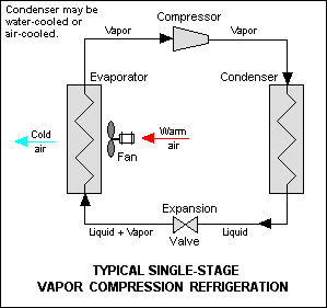
What is Refrigeration ?

Image
The term refrigeration means cooling a space, substance or system to lower and/or maintain its temperature below the ambient one. In other words, refrigeration is artificial cooling. Energy in the form of heat is removed from a low-temperature reservoir and transferred to a high-temperature reservoir . Refrigeration may be defined as the process of achieving and maintaining a temperature below that of the surroundings, the aim being to cool some product or space to the required temperature. One of the most important applications of refrigeration has been the preservation of perishable food products by storing them at low temperatures. Refrigeration systems are also used extensively for providing thermal comfort to human beings utilizing air conditioning. Air Conditioning refers to the treatment of air so as to simultaneously control its temperature, moisture content, cleanliness, odor, and circulation, as required by occupants, a process, or products in the space.  1. Natural Cooli...

Compressor controls

About compressor controls Since compressed air is generally required in varying quantities at the relatively constant pressure, compressor regulators or controls are used to vary the  delivery of the compressor. if the pressure rise too high , The pilot (pressure responsive device) operate to reduce the air delivery. If pressure falls too Low, The pilot operated to increase the delivery of air. Several mechanisms are used as unloading devices to very the delivery of compressed air. (1) the inlet valves may be held open during both the suction and compression stroke -  thus no air  will be compressed in the cylinder. (2) clearance pockets may be used which are automatically controlled by the pilot ,reducing the volume of compressed air delivery. (3) on rotary compressor, a valve which completely closed  the intake line, prevent the intake of air. (4) on some compressors the speed is varied in response to pressure changes on the pilot.  as the  volume of outp...

Compressor cooling

Air or gas compression causes temperature increase which become high enough to cause trouble with the lubrication of the cylinder piston and packings. Cooling  of the air and of the compressor cylinder reduce this problem and also the required work of compressions,approaching  the minimum of an isothermal process. WHAT IS ISOTHERMAL PROCESS an isothermal process is, thermodynamic   process  in which the temperature of a system remains constant. The transfer of heat into or out of the system happens so slowly that thermal equilibrium is maintained. At a particular constant temperature, the change of a substance, object or system is known as Isothermal Process.  In general, during an isothermal process there is a change in internal  energy ,  heat energy , and  work , even though the temperature remains the same. Something in the system works to maintain that equal temperature. This may be done by circulating atmospheric air or water over the cylind...

Non lubricated compressors

Non Lubricated Compressors where high pressure purity is required, as instrumentation air systems,non lubricated compressor should be used or consider. The reciprocating compressor is available as a non lubricated model with carbon or Teflon rings. new filtering problems may arise due to the type of oilless design used, such as carbon dust from worn carbon rings in the compressor. also, multistaging may be required to attend a desired pressure due to temperature limitation. Rotary liquid piston and centrifugal compressors eliminate the need for lubricating oil or oilless design since no internal lubrication is required on either type. initial cost of the liquid piston compressor is higher but is offset by reduced maintenance cost.  With water as a ceiling medium no after cooler is needed to remove the heat of compression or foreign matter which may be present in the incoming air. This non lubricated Teflon ring allows reciprocating compressor to be operated without lubrication that...

Axial flow compressor

Image
Axial flow compressor axial flow compressor is a must see with aerodynamically shaped,radial  blades in both rotor and casing air passes into the machine through The first row of rotor blades and is then redirected into the next and successive Rows by alternates rows of fixed diffusing blades in the casing. flow rating as high as 1,000,000  cubic feet per minute for pressure similar to those of centrifugal machines are available. Axial flow machines are characterized by ess entially constant volume delivery at variable pressure, whereas centrifugal machines deliver practically constant pressure over a variable capacity range . these machines are rarely used for instrument air systems.

working of Centrifugal compressor

Image
 Centrifugal compressor In a multistage centrifugal compressor with intercooler, air  enters the first stage compressor casing  and passes into the eye or centre of the first stage impeller. The rotation of the impeller imparts a high velocity to the air as it moves  radially outward into the diffuser or intercooler area where its temperature is reduced. The air  is then directed into the eye of the second stage impeller where more compressions takes place and similarly to each stage of the machine.  multistage-centrifugal air compressors are generally used for handling large air volumes at pressures up to 150 PSI and higher . centrifugal compressors are often used for  instrument air services.multistage units can handle large air volumes at pressure to 150 psig and higher.

What are dynamic compressors?

 Dynamic compressors Dynamic compressor are machines in which air or gas is compressed by the dynamic action of rotating blades or vanes which accelerate and compressed gas .  Some pressure increase result directly as the gas velocity is increased due to its acceleration by the blades.as the gas pass into the diffuser section of the compressor, the large part of velocity head is recovered as the pressure increase accompanied by a corresponding velocity decrease. centrifugal and axial flow compressor are included in this classification. dynamic compressors are characterized by large volumetric capacity and relatively low pressure, although higher pressure are produced by multistage machines.  Both centrifugal and axial compressors inherently high speed machines.

Liquid piston cylinder ( rotary compressor)

Image
 Liquid piston cylinder compressor  The compressing medium in this unit is a liquid usually water.  the plates of the rotor form a series of buckets carrying the liquid around elliptical casing. The liquid following the control of the inside of the casing surges back into the pockets at the narrow section the air in the pockets is compressed and discharge to properly located ports. With continuous rotation the ring of liquid surges out of the bucket in two broad section of the casing and a new load of air is drawn in through the inlet ports and the cycle begin again. Two compression cycles are completed per revolution. these units are available in 50 to 100 psig pressure ranges  at flow 20 to 450 standard cubic feet per minute .

Screw compressor (rotary compressor)

Image
 Screw compressor In screw compressors two helical rotors turn freely with a controlled clearance between the rotors and the housing oil is injected into the compression chamber to provide lubrication and compression seal. This crew compressor is available at pressure 200 PSIg in flow ranges from 400 to 100  scfm . Most of this oil is removed in some type of air receive or oil separator for use in the compression process. At pressure of 100 PSIg  the flow  range is 400 to 1300 standard cubic feet per minute .

Rotary compressor (sliding vane type)

Image
Sliding vane type rotary compressor   In a sliding vane compressor ,an eccentrically mounted cylindrical slotted rotor turn within a large diameter housing as shown in the figure. Rectangular vanes  slide in and out of the rotor slots and are held against the casing wall by centrifugal force as the rotor turns, air is compressed between the vanes and discharge through a port on the compression side.  Oil is injected into the compression chamber to provide lubrication and a compression seal. most of this oil is remove in an oil/air separator for reuse in the compression process. This type compressor produce pressure up to 125 psig in one or two stage at flows of 100 to 600 standard cubic feet per minute. This is not likely to be used is specially for instrument air but might be used in a system from which in instrument air is taken.

how to work Reciprocating compressor

Image
 Reciprocating compressor Reciprocating compressor is a type of positive displacement compressor.We know that   positive displacement compressor are machine in which successive volume of air or gas are confined within a closed space. A reduction in a volume of this   space  result in an increase in the gas pressure. The  reciprocating compressors are probably the most common of all the types of compressor. it comes in many sizes and configuration such as a single or double acting ,single or multi cylinder with  cylinders arrange in a number of different ways. The trunk type reciprocating air compressor operate similarly to the two cycle engine with the exception that the crank shaft is driven from an external source. No fuel is injected into the cylinder and the compressed gas is discharge at the peak of the compression stroke into a storage receptacle. How to two  cycle engine work A  two-stroke  (or  two-cycle )  engine ...